Note: This article may be accessed and used by installers of various Lumin- and ABB-branded products. In this article, the words "ReliaHome" and "Lumin" are interchangeable. If you have arrived at this article via QR code, use caution when linking to other parts of this knowledge base as other material in this specific library may not be applicable to your installation.
Outlinks to product-specific knowledge bases:
- ABB ReliaHome Smart Panel
- Lumin Panel Guard/Off-Grid Manager (Lumin products manufactured after Q3 2025)
- Legacy Lumin Smart Panel (prior to Q3 2025)
A successful installation hinges on correct CT data, which requires three elements:
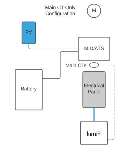
- CTs being placed at the correct location within the wiring system. Most often, CTs will be placed on the feeders to the protected load panel ReliaHome/Lumin is controlling as shown in the graphic below. See CT configurations for more details.
- CTs being oriented correctly. In almost all cases, this involves orienting the "This side toward grid" sticker on one face of each CT to face the utility meter.
- Ensuring that each CT is placed on the correct leg (A or B) of the circuit being monitored. This is sometimes called CT phasing or CT placement by leg. This article addresses this important step of CT installation.
Important: The feeder on the left is not always Leg A!
Lumin/ReliaHome convention is that the top breaker row is always Leg A. The second breaker row is always B. The top bus bar is always fed by the left bus bar, but the left bus bar is not always fed by the feeder conductor on the left if a main breaker is present. This is because there are two types of main breaker types: straight bussing breakers and crossover bussing breakers. Straight bussing breakers pass electricity from the feeder lug on the left to the bus bar on the left and from the feeder lug on the right to the bus bar on the right. Crossover bussing passes electricity from the feeder on the left to the bus bar on the right and from the feeder on the right to the bus bar on the left. See the illustration below:
straight bussing crossover bussing

It is not possible to look at a main breaker and tell if it is a straight bus or crossover type. You must test with a voltmeter with the breaker closed.
Procedure:
Test for AC voltage between the left lug and the left bus bar (shown below).
If voltage is near 0, the breaker is a straight bus type. Place CT A on the left feeder and CT B on the right feeder.
If voltage is approximately 240, the breaker is a crossover type. Place CT A on the right feeder and CT B on the left feeder.

Important: Validate CT placement by checking for positive CT readings in the app before leaving the site.
Additional CT Resources:
CT Configuration Options
Was this article helpful?
That’s Great!
Thank you for your feedback
Sorry! We couldn't be helpful
Thank you for your feedback
Feedback sent
We appreciate your effort and will try to fix the article