TABLE OF CONTENTS
- Grid Detection Circuit Installation Overview
- Grid Detection Circuit Installation Example
- GDC Connections on Sol-Ark Systems
- GDC Connections on EG4 Systems
- GDC Connections with Tesla Backup Switch
Grid Detection Circuit Installation Overview
The ReliaHome Smart Panel Grid Detection Circuit (GDC) must be installed in order for Off-Grid Manager to function (unless an equivalent software-based grid status indication from the inverter is configured, as described below). Until the GDC is energized for the first time, Off-Grid Manager will not appear as an available feature in the ReliaHome mobile app or web portal.
The GDC consists of two AWG #12 wires, one black and one white, that extend out of the flexible conduit that comes pre-installed with the ReliaHome Smart Panel. These two wires are both labeled GRID. The neutral white wire should be landed on the closest neutral bar to the black wire's point of connection to the site wiring.
The GDC functions by detecting voltage in a portion of the electrical system that is on the line/utility side of an automatic transfer switch or microgrid interconnection device (e.g., Tesla Gateway). The GDC includes a relay that sends a signal to the ReliaHome Smart Panel when grid voltage is lost, activating Off-Grid Manager. Do not connect the GDC to any portion of the system backed up by batteries or other on-site backup power.
Note that only one GDC is required per installation location. This circuit can be branched off to each ReliaHome Smart Panel at the location so that they all get the same signal regarding the presence or absence of the grid.
One method of installation is simply to locate a load center that is not backed up by a battery and thus will lose power in the case of an outage. If such a load center is present, the GDC black wire can be landed on its own circuit breaker or pigtailed to an existing circuit where allowed by code. There is virtually no current in the GDC circuit, so it may be connected to any breaker that protects the wire (AWG #12).
When non-backed up circuit breakers are not available, the black wire may also be terminated by tapping non-backed-up feeder conductors that are on the load side of the service disconnect but outside of the Energy Storage System. Ensure proper and code-compliant overcurrent protection is applied when making such a connection.
When no connection can be made on the load side of the service disconnect, the GDC black wire may be connected to a service entrance conductor. Note that this procedure is inherently dangerous and must only be done by qualified personnel. If you are unsure about proper methods for code-compliant supply-side connections for energy management systems, do not proceed.
Grid Detection Circuit Installation Example
Note: This is an example from the field. Confirm local requirements for supply-side connections and service-rated overcurrent protection/disconnects with your local Authority Having Jurisdiction.
1. Locate a supply-side connection point inside an enclosure.
|  |
2. The connection to a service entrance conductor is made with an insulated piercing connector (IPC).
|  |
The National Electric Code requires that supply-side connections to service wiring use a minimum wire gauge of AWG 6. When connected to the service entrance conductors, this connection must feature a service-rated disconnect so that the GDC can be safely de-energized. It is also necessary to protect the supply-side connected GDC with an overcurrent protection device, which can be integral to the service-rated disconnect or can be a separate device located immediately on the load side of it. A typical approach is to make the connection with a short length of #6 and run that to a service-rated fused disconnect with a fuse appropriately sized to protect the smallest conductors in the GDC. Lumin GDC wiring is 12 AWG and would typically be protected with an OCPD with a rating of no more than 20 amperes. As there should never be any current on the GDC, smaller OCP ratings are acceptable and will not trip/blow under normal conditions.
Only once the GDC is successfully installed will Off-Grid Manager become available in the ReliaHome mobile app and web browser.
Grid Detection on Sol-Ark Systems
In some installations it can be difficult to find a suitable place to land the Grid Detection Circuit. All common Sol-Ark inverters provide two viable options for obtaining grid status, using the grid status indication from the Sol-Ark integration and wiring the ReliaHome Smart Panel Grid Detection circuit to the inverter's GEN input. These are discussed in detail below:
Grid Status from the Sol-Ark integration
The ReliaHome Smart Panel can utilize Sol-Ark's own grid status indicator once a Sol-Ark battery integration has been configured. Setting up this integration is required in order to leverage state-of-charge-based load shedding, and grid status can be obtained with no additional installation effort. There is no need to run the Grid Detection Circuit if using this option. The grey GDC wiring can simply be coiled and tucked into the load center as it is not required. Follow the instructions for the Sol-Ark battery integration here and ensure that Sol-Ark Grid Status is configured.
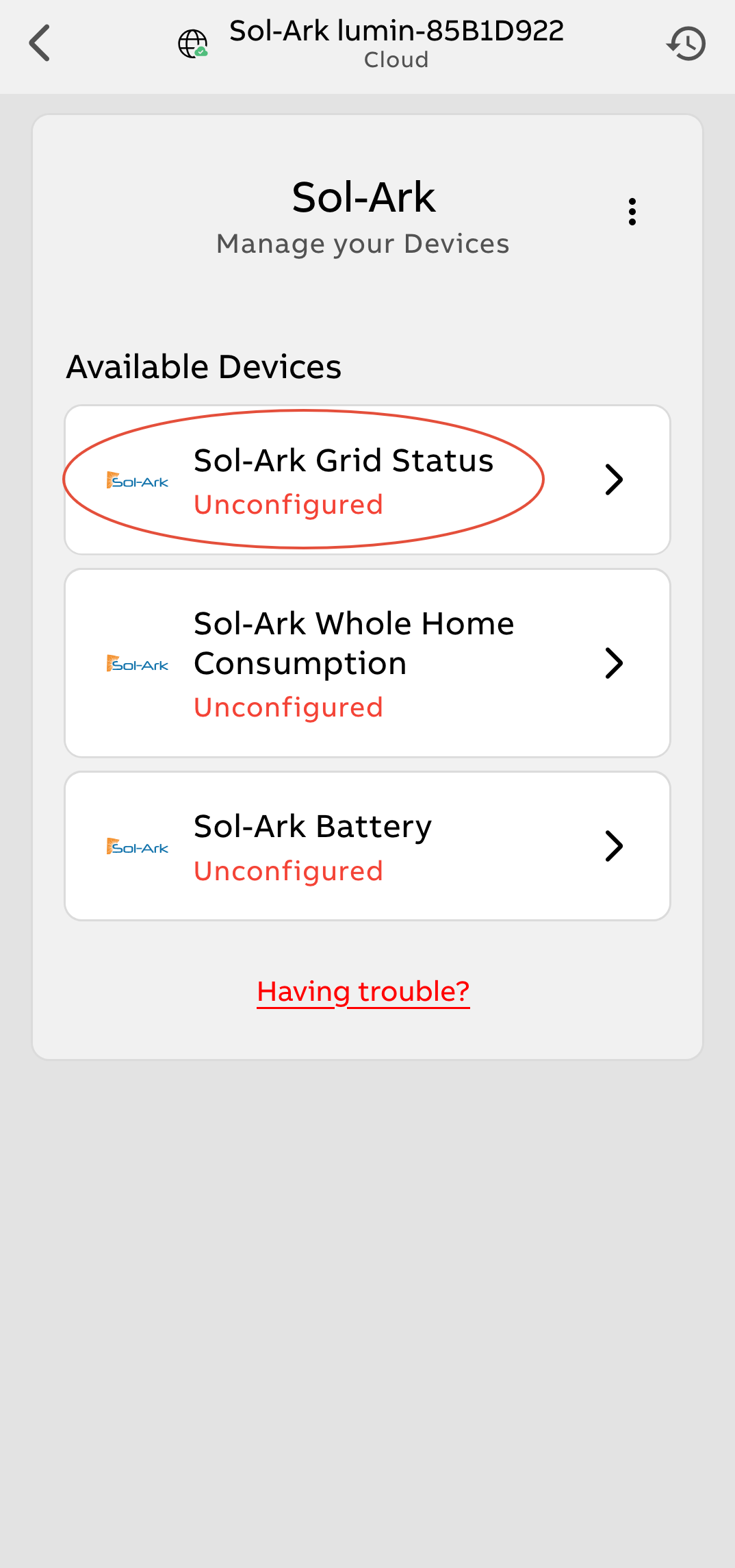 | 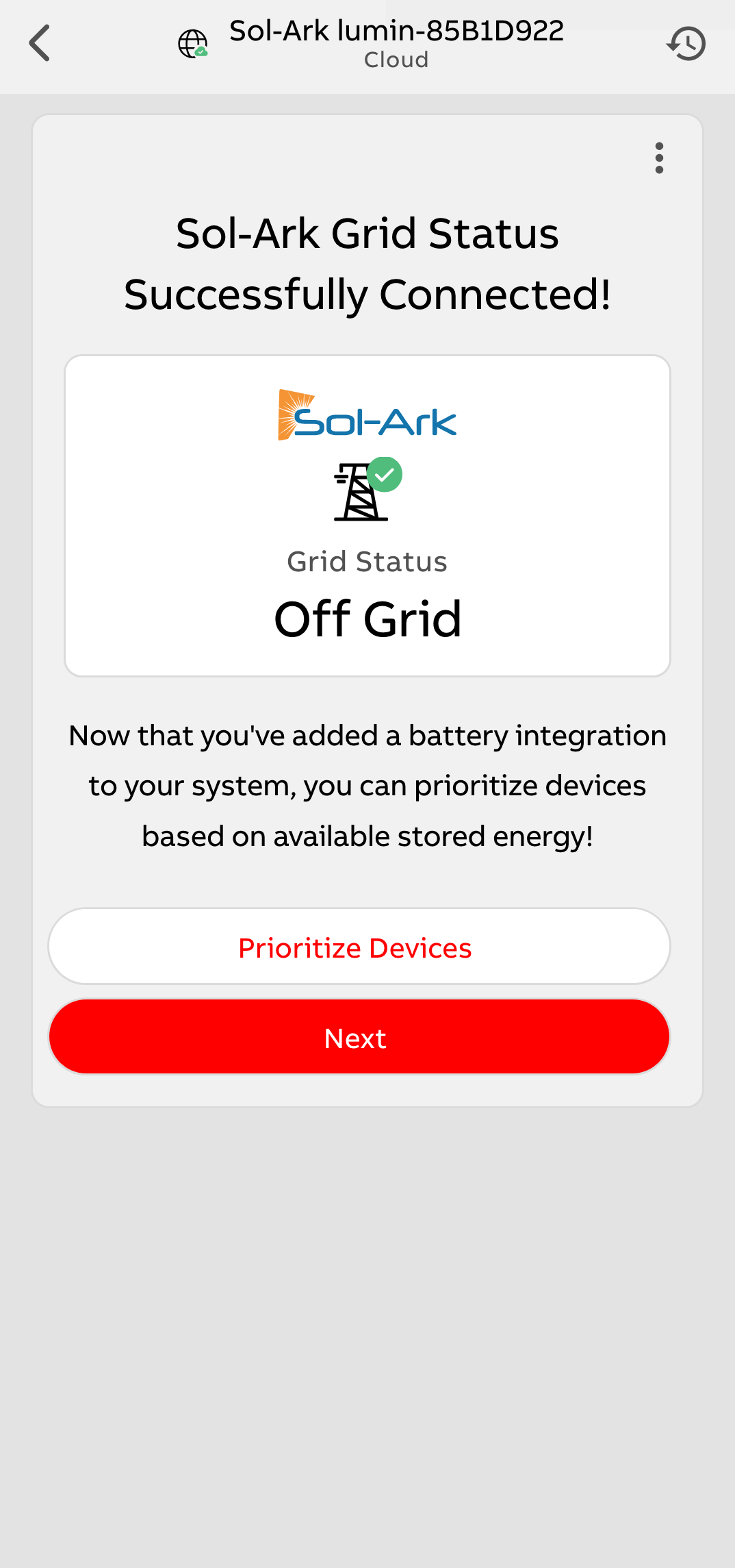 |
ReliaHome Grid Detection Circuit run to Sol-Ark GEN Input terminals
These terminals loses voltage during a grid outage and properly activate the GDC if the GEN input is configured correctly in the Sol-Ark settings. This configuration will only work if the GEN input is not being used for any other purpose such as a generator connection. Note that this method is not required if grid status is obtained from the Sol-Ark integration as described above.
| 1. Locate the terminal labeled "L1 GEN" in the Sol-Ark wiring space. Connect the Lumin black wire labeled "Grid Line" to this terminal via an appropriately sized transition wire. NOTE: The GEN terminal can accept wire gauges between 2 and 4/0 AWG. The ReliaHome GDC is 12 AWG. There should never be any current on this circuit; in this application it is being used for voltage sensing only, so 12 AWG is not undersized. However, it is critical to use the specified wire size on the Sol-Ark GEN terminal. A common approach is to use a short length of 2 AWG at the GEN terminal and splice it to the ReliaHome GDC black wire (12 AWG) using an approved splicing method. The portion of the GDC circuit inside the ReliaHome Smart Panel contains a 1-A fuse that will protect the smaller-gauge ReliaHome wiring should it become accidentally energized. |
| 2. Connect the white Lumin wire labeled "Grid Neutral" to the neutral busbar in the Sol-Ark wiring space. |
3. In the inverter's display menu, open the System Setup Menu by tapping the setup icon: |
| 4. On the Smart Load screen, select the checkboxes for "AC Coupled Input to Gen" AND "On-Grid always on". All other checkboxes must remain unchecked. |
| 5. Set "Smart Load OFF Batt" to 5% and "Smart Load On Batt" to 0%. |
| This configuration will cause the GEN terminals to lose voltage when grid power is lost, activating the Smart Panel's Smart Power Mode. |
GDC Connections on EG4 Systems
18KPV-12LV
In some installations it can be difficult to find a suitable place to land the Grid Detection Circuit. EG4 18KPV-12LV inverters provide a viable option for GDC connection: the inverter's GEN input. When properly configured this terminal loses voltage during a grid outage. This configuration will only work if the GEN input is not being used for any other purpose such as a generator connection.
| 1. Locate the terminal labeled "L1 GEN" in the Sol-Ark wiring space. Connect the Lumin black wire labeled "Grid Line" to this terminal via an appropriately sized transition wire. NOTE: The GEN terminal can accept wire gauges between 2 and 4/0 AWG. The Lumin GDC is 12 AWG. There should never be any current on this circuit; in this application it is being used for voltage sensing only, so 12 AWG is not undersized. However, it is critical to use the specified wire size on the Sol-Ark GEN terminal. A common approach is to use a short length of 2 AWG at the GEN terminal and splice it to the ReliaHome GDC black wire (12 AWG) using an approved splicing method. The portion of the GDC circuit inside the ReliaHome Smart Panel contains a 1-A fuse that will protect the smaller-gauge Lumin wiring should it become accidentally energized. |
| 2. Connect the white ReliaHome wire labeled "Grid Neutral" to the neutral busbar in the EG4 wiring space. |
3. In the inverter's display menu, open the System Setup Menu by tapping the setup icon: |
| 4. On the Smart Load screen, select the checkboxes for "AC Coupled Input to Gen" AND "On-Grid always on". All other checkboxes must remain unchecked. |
| 5. Set "Smart Load OFF Batt" to 5% and "Smart Load On Batt" to 0%. |
| This configuration will cause the GEN terminals to lose voltage when grid power is lost, activating the Smart Panel's Smart Power Mode. |
Grid Sensing with Tesla Backup Switch or Inaccessible Grid Wiring
Some installations may feature wiring that cannot be accessed for purposes of connecting a Grid Detection Circuit. This can happen when the wiring between the meter and the Tesla Gateway is impractical to access. It also happens anytime the Tesla Backup Switch (BUS) is installed. The BUS is a Microgrid Interconnect Device (MID) that integrates onsite renewables, battery power, and grid power at the meter base. This leaves no wiring within the home that will lose voltage in an outage and does not allow the connection of a hardwired Grid Detection Circuit.
When a Grid Detection Circuit is difficult to install for any reason, Tesla installers should rely instead on the grid status provided by the ReliaHome Tesla integration, which provides this value to the ReliaHome Smart Panel via an API call. This may result in some latency as the API call is made once every 30 seconds, but in most installations this short delay in activating Off-Grid Manager does not present a problem.
Was this article helpful?
That’s Great!
Thank you for your feedback
Sorry! We couldn't be helpful
Thank you for your feedback
Feedback sent
We appreciate your effort and will try to fix the article