
TABLE OF CONTENTS
- INTRODUCTION
- IMPORTANT SAFETY INSTRUCTIONS -READ BEFORE USE
- WIRELESS COMMUNICATION
- NETWORK COMMUNICATION
- CONSIDERATIONS BEFORE INSTALLATION
- SUPPORT AND RESOURCES
- TECHNICAL SPECIFICATIONS
- INCLUDED MATERIALS
- REQUIRED TOOLS AND MATERIALS (NOT INCLUDED)
- INSTALLATION PROCEDURE
- MOBILE APP CONFIGURATION
- LIMITED WARRANTY FOR RELIAHOME FLEX
- RADIO FREQUENCY STATEMENT
INTRODUCTION
ReliaHome Flex is a modular energy management system. It is designed to control residential electric loads to optimize energy consumption. ReliaHome Flex consists of two module types, a Hub Module and a Controller Module. The Hub Module creates a wireless network within the home to connect up to five Controller Modules, each of which is installed in line with a branch circuit to control an electric load.
IMPORTANT SAFETY INSTRUCTIONS - READ BEFORE USE
 | WARNING! HAZARDOUS VOLTAGES PRESENT THAT CAN CAUSE ELECTRIC SHOCK, BURNS, OR DEATH. DO NOT HANDLE, INSTALL, USE, OR SERVICE THIS PRODUCT UNTIL YOU HAVE READ THESE INSTRUCTIONS. |
 | WARNING! READ THIS DOCUMENT CAREFULLY AND OBSERVE THE FOLLOWING SAFETY PRECAUTIONS BEFORE INSTALLING OR USING THE SOFTWARE. |
Observe the following safety precautions:
● Installation and servicing must be conducted by a Qualified Person, according to local and national electrical codes.
● Certified Installer training must be completed before beginning installation. Only Certified Installers can complete the in-app configuration necessary for proper operation. See Installation Step 1 for a link to installation training.
● Review this entire manual before starting the installation or servicing process.
● Personal protective equipment should be utilized when installing or servicing the product.
● Do not use the product in any way other than its intended use.
● Do not install or operate the product outside the conditions specified in this manual and product labels.
● Do not open, attempt to access, or touch any internal product parts except as instructed by this manual. Improper access can introduce damaging static charges to sensitive electronics and will void the warranty. Dangerous voltages could be encountered even when breakers are open.
● Do not use the product if it is damaged or appears to be damaged.
● Operate the Hub Module using only the included power supply.
● For outdoor installation of the Controller Module, utilize suitable approved fittings and preserve weather-proofing integrity.
● Adhere to all relevant local and national safety regulations for electrical work.
● Review ReliaHome Flex technical specifications.
WIRELESS COMMUNICATION
Communication between Flex modules occurs in the 900 MHz band. The network signal created by the Hub Module is not blocked by typical building materials and can travel far enough to reach modules placed at the distant end of a home or even an outbuilding. Communication on this network is not affected by congestion on the home’s general-use WiFi network. Modules are secured through encrypted communication and must be paired through the configuration steps listed in this manual.
A certified installer must use a mobile device connected to the home's WiFi network to configure or reconfigure the system.
NETWORK COMMUNICATION
ReliaHome Flex must be connected to the customer’s internet to function. Internet connectivity is required to control the system through the ReliaHome app when away from the home. Internet access is also required to participate in utility programs.
If the internet connection goes down, Flex will still safely operate but will be unable to accept updates, receive newly scheduled utility programs, or be controlled remotely until the network is restored. Local control is still possible with a mobile device connected to the same Local Area Network (LAN) as the ReliaHome Flex hub.
CONSIDERATIONS BEFORE INSTALLATION
Required for installation:
● A smartphone or tablet with a camera. The ReliaHome Flex system cannot be configured without a mobile device.
● Access to the home’s router for connecting the Hub Module ethernet cable.
● Access to the WiFi network name and password for connecting your mobile device. Configuration must be done locally while connected to the home's WiFi network.
● Access to indoor exposed wiring for the circuit desired to be controlled. ReliaHome Flex is not designed to be flush mounted (i.e., set within drywall).
● Installation time varies: The Controller Module may be installed in less than 15 minutes in ideal conditions (e.g., readily accessible Romex cable), while more complex installations may take more than 1 hour (e.g., existing conduit).
● Configuration of the Hub Module and ReliaHome app will take approximately 10 minutes for new systems.
Limitations of Flex:
ReliaHome Flex is able to be installed in homes with backup power but is not designed primarily to limit power usage to stay under inverter capacity. Currently, ReliaHome Flex only integrates with Tesla Powerwall for off-grid battery management. Use the ReliaHome Smart Panel (ABBHEM2) to manage other battery systems.
SUPPORT AND RESOURCES
For installation assistance, please contact Support by email at support@reliahome.abb.com or by phone at 1-888-421-0616 (North America). Technical support is available 9 a.m. to 6 p.m. Eastern Time, Monday-Friday. Troubleshooting and support documentation can be accessed at support.reliahome.abb.com
TECHNICAL SPECIFICATIONS
Specification | Value |
|---|---|
Installation Type | Controller: Surface mount; Indoor/outdoor Hub: Indoor only |
Time requirement | 10 minutes for hub, 15-80 min per controller |
Temperature | -20 °C to 70 °C (-4 °F to 158 °F) |
Hub dimensions | 5.5 × 5.5 × 1.8 in |
Controller dimensions | 2.8 × 9.3 × 3.9 in |
Electrical system | 120/240 VAC (±10%); 50-60 Hz |
Max breaker size | 60 A; Deratings apply above 50 °C (122 °F) |
Breaker types | Single pole (120 V load) and double pole (240 V, 208 V, 120/240 V or 120/208 V load) |
Cable types | NM (Romex), MC (metal-clad); 14-6 AWG |
Module communications | Segregated 900MHz Mesh Network; 256-bit AES CBC Encryption |
Network connection | Ethernet (required for hub only) |
Ethernet port | 1×Rj-45 (10/100 mbps) |
IP addressing | Dynamic (DHCP) |
Cryptographic system | TLS 1.2 (minimum) |
User access | ReliaHome app iOS, Android, and Web |
| Warranty | Five-year limited. See Warranty section |
Product safety | NRTL/C Listed to UL 916; and CSA C22.2 No. 205 |
Radio frequency | 47 CFR 15 (FCC), RSS-Gen and RSP-100 (ISED) |
INCLUDED MATERIALS
 ReliaHome Flex Hub Module (antenna included but packaged separately) ReliaHome Flex Hub Module (antenna included but packaged separately) |  Ethernet Cable Ethernet Cable |  Power Supply Cable Power Supply Cable |
 ReliaHome Flex Controller Module ReliaHome Flex Controller Module |  Supplemental Documents: Supplemental Documents:Quick Install Guide Setpoint Label Full-Scale Install Template |  Hardware Bag: Hardware Bag:External Mounting Tabs (x4 per Controller Module) Mounting Tab-to-Controller Module Screws (x4 per Controller Module) |
REQUIRED TOOLS AND MATERIALS (NOT INCLUDED)
 Wire cutters Wire cutters |  Wire strippers Wire strippers |  Pliers Pliers |
 Voltage Tester Voltage Tester |  Screwdriver Screwdriver |  Pen or Marker |
 Tape Measure |  Utility Knife Utility Knife | 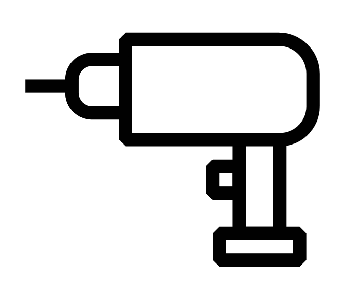 Drill/Impact Driver Drill/Impact Driver |
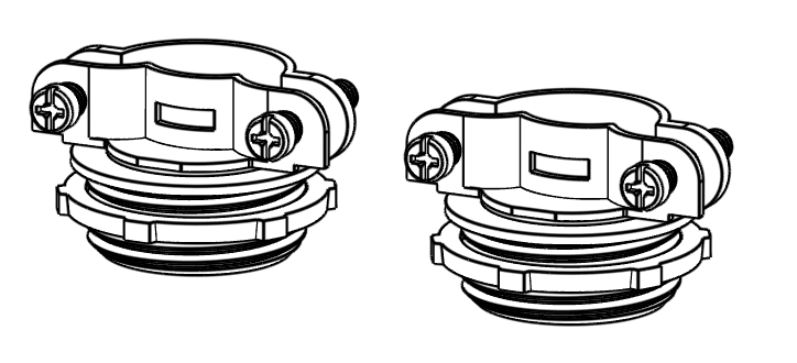 Cable Connectors (x2 per Controller Module) |  Wiring Support/Strain Relief Hardware (x2 per Controller Module) Wiring Support/Strain Relief Hardware (x2 per Controller Module) |  Surge Protective Device (SPD) Surge Protective Device (SPD) |
 Step Bit or Hole Saw Step Bit or Hole Saw |  4 mm Hex Wrench 4 mm Hex Wrench | 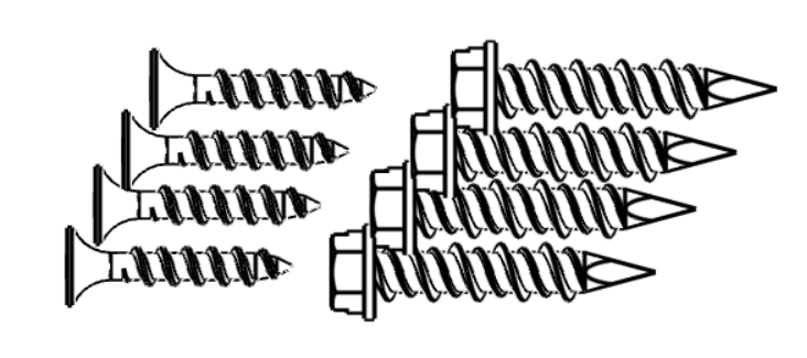 Wood screws or Concrete Anchors Wood screws or Concrete Anchors |
INSTALLATION PROCEDURE
| Installation Step 1 | Become a Certified Installer by taking the required installer training course on the ReliaHome Learnworlds training. |  |
| Installation Step 2 | Ensure that the mobile device being used with the ReliaHome app is connected to the home WiFi network associated with the router with the ethernet connection to the Hub Module. | 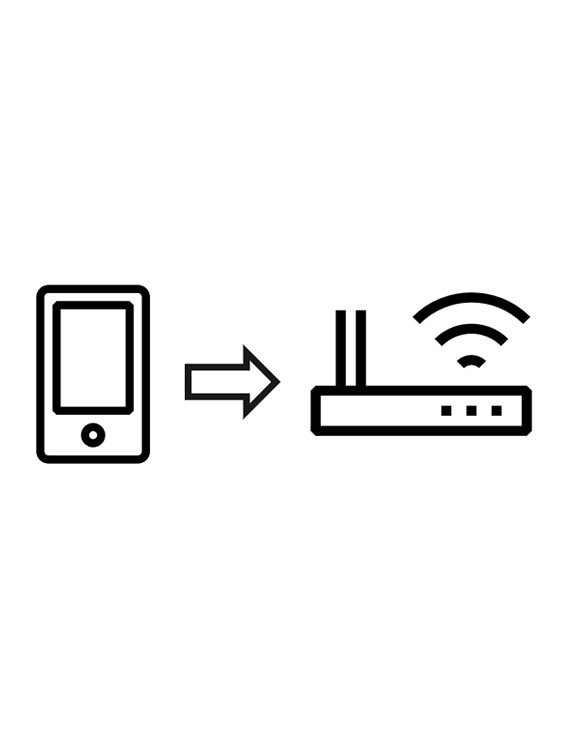 |
| Installation Step 3 | Unpack the Hub Module and included cables. Check that all materials are included in the box.
|
|
| Installation Step 4 | Screw the antenna onto the Hub Module until finger tight. Do not use excessive force. For best wireless transmission, angle the hinged antenna so that it is perpendicular to the Controller Modules. |  |
| Installation Step 5 | Use the supplied wall adapter and Ethernet cable to connect the Hub Module to power and Ethernet. The hub ethernet is normally connected to the home’s wireless router. Once the ethernet cable is connected, the ethernet light on the Hub Module will be solid. The cloud light on the Hub Module will blink until at least one Controller Module is paired with the Hub Module. For more information about the meaning and status of the indicator lights, refer to the ReliaHome Flex Button Functions support article. | 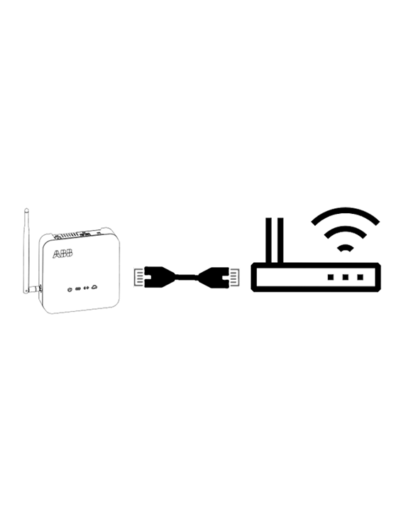 |
| Installation Step 6 | Ensure that a whole-home Surge Protective Device (SPD) from ABB's Residential SPD product line is installed. While not required for normal functionality of the ReliaHome Flex system, an SPD protects the energy management system and other sensitive electronics against preventable damage from lightning strikes. Lightning damage is not covered by the ReliaHome Flex product warranty. Note: ABB offers a wide variety of SPDs for every installation, including: THQLSURGE2: Designed for convenient plug-in compatibility with ReliaHome or PowerMark load centers and features 25 kA per phase surge current protection. THQLSURGE5: Designed for convenient plug-in compatibility with ReliaHome or PowerMark load centers and features 50 kA per phase surge current protection. THQLSURGEP5: Designed for convenient plug-on neutral compatibility with ReliaHome load centers and features 50 kA per phase surge current protection. THQLSURGEP7: Designed for convenient plug-on neutral compatibility with ReliaHome load centers and features 75 kA per phase surge current protection. THOMESURGE: Designed for use with any load center and features 36 kA per phase surge current protection. SPDs with higher kA ratings offer more protection and higher-value connected equipment warranties for minimal additional cost. |  THQLSURGEP7 and THOMESURGE THQLSURGEP7 and THOMESURGE |
| Installation Step 7 | Unpack the Controller Module and included hardware. |  |
| Installation Step 8 | Select a location for Controller Module installation where: ● Cable/conduit is exposed over a flat mounting surface with enough area for the Controller Module. Alternatively, wiring concealed behind drywall can be routed into the back of the Controller Module, however this significantly complicates the installation. ● Wire direction (from breaker to load) is apparent. ● Environmental conditions are within the Controller Module technical specifications. ● Cable has sufficient slack and space for routing into the Controller Module. Note: The Controller Module will add 4" to the length of an existing circuit. This typically provides enough slack in existing wiring for routing into the Controller Module. |  |
| Installation Step 9 | (Optional) Write a description of the circuit being controlled as well as the Controller Module serial number on the Install Template if the installation location is difficult to access. This will simplify the pairing process. Avoid mixing up the Install Templates as each template contains a QR code unique to a specific Controller Module. |  |
| Installation Step 10 | Identify the load you wish to control and verify it is functional before proceeding. This will help you ensure that the load has been properly deenergized in the next steps. |  |
| Installation Step 11 | Locate and turn off the associated breaker for the load to be controlled (or the main breaker if neutrals are shared within the home). |  |
| Installation Step 12 |  WARNING! Failure to properly de-energize wiring can result in electric shock, burns, or death. Circuit breakers are often mislabeled. Do not proceed until verifying that the wiring to be cut in the next step has been de-energized by means of a voltage tester and ensuring that the load is not functional. WARNING! Failure to properly de-energize wiring can result in electric shock, burns, or death. Circuit breakers are often mislabeled. Do not proceed until verifying that the wiring to be cut in the next step has been de-energized by means of a voltage tester and ensuring that the load is not functional. | 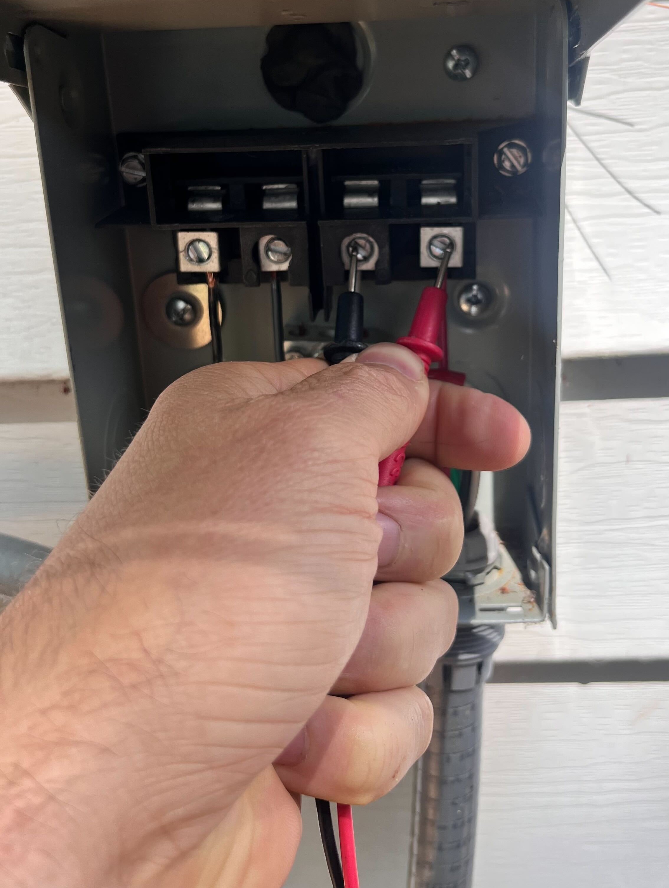 |
| Installation Step 13 | Using the included 1:1 scale Install Template: ● Cut wiring at the center of the installation location. ● Trim the cable jacket so that conductors can be arranged individually, but ensure the cable jacket extends through the cable connector and into the Controller Module enclosure. ● Arrange and trim conductors to fit neatly in the terminals. ● Strip 0.6” of conductor insulation. |  |
| Installation Step 14 | Remove the cover from the Controller Module by loosening the four hex screws on the top of the module using a 4 mm hex wrench. | 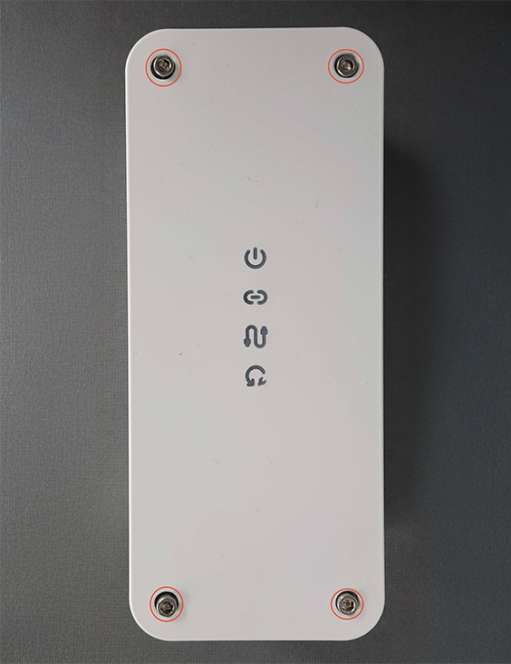 |
| Installation Step 15 | Determine how the Controller Module will be mounted. There are two options: | |
| Installation Step 15(a) | Internal mounting option: Drill mounting screw pilot holes in the four divots located on the interior of the base of the Controller Module. Drilling these holes will violate the raintight integrity of the enclosure and should only be done for indoor or sheltered installations. | 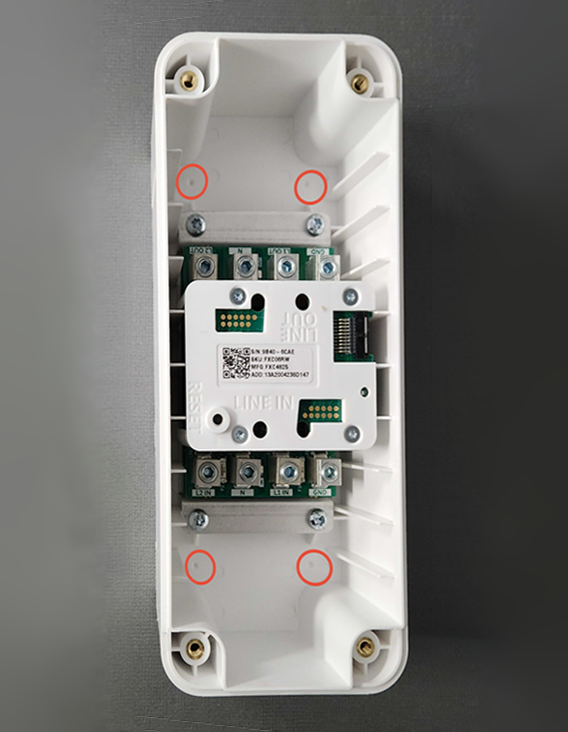 |
| Installation Step 15(b) | External mounting option: Use the provided mounting tab screws to secure the four provided external mounting tabs to the screw bosses integrated into the bottom of the Controller Module. The photo at right shows the mounting tabs installed. | 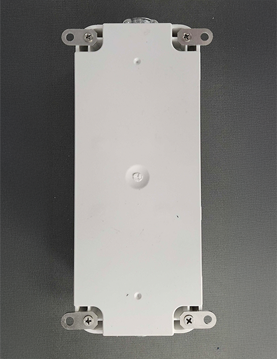 |
| Installation Step 16 | Use a step bit or hole saw with pilot bit to drill holes in the Controller Module enclosure for cable connectors or conduit connectors. There are two options: |  |
| Installation Step 16(a) | Rear-entry option: Use a step bit or hole saw to drill two holes centered on the two small divots on the back of the Controller Module. Holes must be the correct size for the cable connector or conduit connector you will use. After drilling, gently shake or blow out any plastic drill shavings inside the Controller Module. |  |
| Installation Step 16(b) | Side-entry option: Use a step bit or hole saw to drill two holes centered on the two small divots on either of the short sides of the Controller Module. Holes must be the correct size for the cable connector or conduit connector you will use. After drilling, gently shake or blow out any plastic drill shavings inside the Controller Module. | 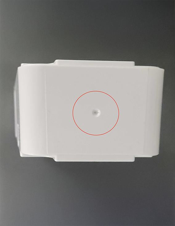 |
| Installation Step 17 | Install listed cable or conduit connectors in the Controller Module. Connectors are not included. | 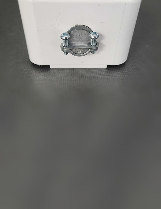 |
| Installation Step 18 | Determine the correct orientation of the Controller Module in the installation location: ● The wire terminals labeled Line In are in the direction of the load center with the associated breaker. ● The wire terminals labeled Load Out are in the direction of the controlled load. |  |
| Installation Step 19 | Mount the Controller Module to the wall using the pilot holes drilled previously and wood screws or concrete anchors (not included). | |
| Installation Step 20 | Referencing the included 1:1 Scale Install Template, route the wiring into the Controller Module through the cable clamps and secure all conductors in the wire terminals using a 4 mm hex wrench. Ensure the wires are connected to the correct terminals labeled: L2 [Line 2] (240 V circuits only) N [Neutral] L1 [Line 1] GND [Equipment Grounding Conductor] Conductor color mapping must be identical for input and output. For example, if a black wire is connected to L1 of the Line In terminal, a black wire must connect to L1 of the Line Out terminal. | |
| Installation Step 21 | Torque wire terminals as follows: 4-8 AWG: 45 inch-pounds 10-14 AWG: 35 inch-pounds | |
| Installation Step 22 | Tighten the cable connectors to secure the connected cable (if applicable). The combination of cable and fitting must entirely cover openings to prevent contact with hazardous voltages after installation. | |
| Installation Step 23 | Ensure that the wiring or conduit is properly secured to the wall on both the line and load sides of the Controller Module. Typically non-metallic cabling must be secured within 12 inches of enclosure entry and electrical metallic conduit (EMT) must be secured within three feet, but check local code requirements. | |
| Installation Step 24 | Install the cover back on the Controller Module. Use the previously removed screws to secure the cover. Note that the cover can be secured in either orientation that matches the body of the controller Module. Users may find it more intuitive if the power light is the top-most or left-most of the indicator lights. |  |
| Installation Step 25 | Turn on the associated breaker. |  |
| Installation Step 26 | Confirm that the blue power indicator light is illuminated through the cover of the Controller Module. If no indicators are lit, wiring may have been reversed: ensure that the conductors from the load breaker have been installed on the "Line In" terminals. |  |
| Installation Step 27 | Proceed immediately to the Mobile App Configuration steps below. The controlled load will not function until the system has been properly configured in the app. |  |

MOBILE APP CONFIGURATION
| Configuration Step 1 | Download the ReliaHome mobile app from the App Store or Google Play Store. Note: Do not download the ReliaHome Solar+ app. The correct app contains the letter “e” in the depiction of a house in the app icon. |  |
| Configuration Step 2 | Open the ReliaHome app and select Create Account or Login (if an account has already been created). Ensure that the email address used for the account is the same one used for this Certified Installer training. If this is your first ReliaHome (or Lumin) installation, follow the link in the account activation email you receive. |  |
| Configuration Step 3 | Select New Installation to start your installation. |  |
| Configuration Step 4 | Accept Location, Camera, and Local Connectivity on the Permissions Required screen and select Next. |  |
| Configuration Step 5 | Select ReliaHome Flex Hub in the hardware configuration selection. |  |
| Configuration Step 6 | Select either Panel Guard or Off-Grid Manager, depending on the intended use of the installation. Note Off-Grid Manager for ReliaHome Flex currently only works with Tesla Powerwall systems. Press Next to proceed. |  |
| Configuration Step 6 | Click Setup once the Hub Module you are installing is discovered. The Hub Module will automatically download any required updates once connected. |  |
| Configuration Step 7 | Select Continue on the "Successfully Created!" screen. |  |
| Configuration Step 8 | In the Configuration Checklist, select System Information. |  |
| Configuration Step 9 | Input System Settings and tap Save. |  |
| Configuration Step 10 | In the Configuration Checklist, select User Access. |  |
| Configuration Step 11 | Add homeowner emails and tap add. |  |
| Configuration Step 12 | Users invited in the previous step will receive a welcome email from which they can create an account and access the system. If the users do not see the email several minutes after adding them, ask them to check their email spam folder. |  |
| Configuration Step 13 | In the Configuration Checklist, Select Devices and Integrations. |  |
| Configuration Step 14 | On the Devices & Integrations screen, select Controller Modules. |  |
| Configuration Step 15 | In the list of Controller Modules, select Add New Device. |  |
| Configuration Step 16 | A QR code scanner will appear. Locate and scan the Flex Pairing QR code on the side of the Controller Module. If this QR code cannot be scanned, two other options exist: Option 1: Unscrew and remove the Controller Module cover. Scan the QR code on the rectangular plastic cover between the wiring terminals. (Do not scan the QR code on the underside of the module cover.) Option 2: Scan the QR code on the installation template (provided there is no confusion across multiple Controller Modules; verify serial numbers if needed). |  |
| Configuration Step 17 | In the Configuration Checklist select Panel Guard or Off-Grid Manager. Follow the in-app prompts to correctly configure these modes. Refer to the support solutions library at support.reliahome.abb.com for additional assistance. |  |
LIMITED WARRANTY FOR RELIAHOME FLEX
This Limited Warranty gives you specific legal rights and you may also have other rights, which vary from state to state. ABB warrants that during the warranty period, the products will be free from defects in materials and workmanship. To obtain warranty coverage, you must be the original purchaser and user of the products.
WE LIMIT THE DURATION AND REMEDIES OF ALL IMPLIED WARRANTIES, INCLUDING WITHOUT LIMITATION THE WARRANTIES OF MERCHANTABILITY AND FITNESS FOR A PARTICULAR PURPOSE TO THE DURATION OF THIS EXPRESS LIMITED WARRANTY. SOME STATES DO NOT ALLOW LIMITATIONS ON HOW LONG AN IMPLIED WARRANTY LASTS, SO THE ABOVE LIMITATIONS MAY NOT APPLY TO YOU.
Our responsibility for defective goods is limited to repair, replacement, or refund as described below in this warranty statement.
Who May Use This Warranty?
ABB Inc. (d/b/a ABB), a Delaware corporation located at address 305 Gregson Drive, Cary, NC 27511 (“we”) extends this limited warranty only to the consumer who originally purchased the FXH1W (ReliaHome Flex Hub) or FXC06RW (ReliaHome Flex Controller) through an authorized dealer and can provide proof of purchase in the form of a receipt or purchase order. The warranty is non-transferable.
What Does This Warranty Cover?
This limited warranty covers defects in materials and workmanship of the FXH1W (ReliaHome Flex Hub) or FXC06RW (ReliaHome Flex Controller) (the “products”) for the Warranty Period as defined below. The warranty is valid only when installed in a residential application in compliance with National Electrical Code standards. All connected equipment must be Underwriters’ Laboratories (UL) and/or Canadian Standards Association (CSA) approved. The installation must comply with all applicable electrical and safety codes set forth pursuant to the National Electrical Code (NEC).
What Does This Warranty Not Cover? This limited warranty does not cover any damage due to: (a) transportation; (b) storage; (c) improper installation; (d) improper use; (e) failure to follow a product instructions; (f) failure to adhere to a product’s technical specifications, including a product’s environmental and electrical ratings; (g) modifications; (h) unauthorized opening of a product’s cover; (i) tampering with a product’s internal components; (j) unauthorized repair; (k) normal wear and tear; or (l) external causes such as accidents, abuse, flooding, lightning strikes, storms, or other actions or events beyond our reasonable control. This limited warranty also does not apply to the software, mobile applications, technology and services provided by ABB which enable you to remotely access and view data that is collected, stored and transmitted by the products concerning electricity consumption and/or to remotely control electrical circuits which the products are connected to (the “ABB Service”). Use of the Service is subject to and governed by the terms of the Service User Agreement, a copy of which can be accessed at https://www.luminsmart.com/consentdocumentation/.
Any warranties provided by ABB with respect to the ABB Service are only those warranties expressly set forth in the ABB Service User Agreement.
What Is the Period Of Coverage? The “Warranty Period” for this limited warranty starts on the date the product is first purchased and lasts five years. The Warranty Period is not extended if we repair or replace the applicable product. We may change the availability of this limited warranty at our discretion, but any changes will not be retroactive.
What Are Your Remedies Under This Warranty? With respect to any defective product during the applicable Warranty Period, we will, in our sole discretion, either: (a) repair or replace such product (or the defective part) free of charge or (b) refund the purchase price of such product. We will also pay for shipping and handling fees to return the repaired or replacement product to you if we elect to repair or replace the defective product.
How Do You Obtain Warranty Service? Please contact ReliaHome Energy Management Support at +1-888-421-0616, Monday-Friday 9AM to 6PM EST or email support@reliahome.abb.com to obtain a Return Material Authorization number (RMA) and return material policy.
Limitation of Liability The remedies descried above are your sole and exclusive remedies and our entire liability for any breach of this limited warranty. Our liability shall under no circumstances exceed the actual amount paid by you for the defective product, nor shall we under any circumstances be liable for any consequential, incidental, special or punitive damages or losses, whether direct or indirect.
Some states do not allow the exclusion or limitation of incidental or consequential damages, so the above limitation or exclusion may not apply to you.
RADIO FREQUENCY STATEMENT
This device complies with Part 15 of the FCC rules and with Innovation, Science and Economic Development Canada’s licence-exempt RSS(s). Operation is subject to the following two conditions:
- This device may not cause interference.
- This device must accept any interference, including interference that may cause undesired operation of the device.
L’émetteur/récepteur exempt de licence contenu dans le présent appareil est conforme à la partie 15 des règles de la FCC et aux CNR d’Innovation, Sciences et Développement économique Canada applicables aux appareils radio exempts de licence. L’exploitation est autorisée aux deux conditions suivantes:
- L’appareil ne doit pas produire de brouillage;
- L’appareil doit accepter tout brouillage radioélectrique subi, même si le brouillage est susceptible d’en compromettre le fonctionnement.
Changes or modifications not expressly approved by the party responsible for compliance could void the user’s authority to operate the equipment.
The antennas used for this transmitter must be installed to provide a separation distance of at least 20cm from all persons and must not be located or operating in conjunction with any other antenna or transmitter.
Les antennes utilisées pour ce transmetteur doivent être installé en considérant une distance de séparation de toute personnes d’au moins 20 cm et ne doivent pas être localisé ou utilisé en conflit avec tout autre antenne ou transmetteur.
This radio transmitter 1846A-XBSX (PMN: XBee SX RF Module; HVIN: XBSX) has been approved to operate with dipole type antennas with a maximum gain of 2.1 dBi. Antennas of other types or exceeding the maximum permissible gain are prohibited for use with this device.
NOTE: This equipment has been tested and found to comply with the limits for a Class B digital device, pursuant to part 15 of the FCC Rules. These limits are designed to provide reasonable protection against harmful interference in a residential installation. This equipment generates, uses and can radiate radio frequency energy and, if not installed and used in accordance with the instructions, may cause harmful interference to radio communications. However, there is no guarantee that interference will not occur in a particular installation. If this equipment does cause harmful interference to radio or television reception, which can be determined by turning the equipment off and on, the user is encouraged to try to correct the interference by one or more of the following measures: (1) Reorient or relocate the receiving antenna. (2) Increase the separation between the equipment and receiver. (3) Connect the equipment into an outlet on a circuit different from that to which the receiver is connected. (4) Consult the dealer or an experienced radio/TV technician for help.
Was this article helpful?
That’s Great!
Thank you for your feedback
Sorry! We couldn't be helpful
Thank you for your feedback
Feedback sent
We appreciate your effort and will try to fix the article